Arduino Crosstalk

honcho12

Space Marshal
Oct 12, 2014
600
372
2,410
RSI Handle
honcho12
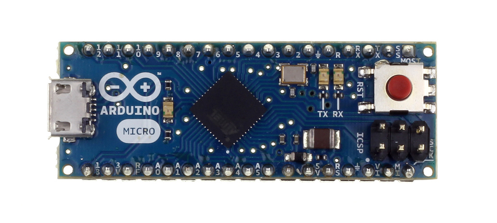
So I'm bumbling my way through turning an arduino into a joystick with MMJoy, but I'm getting wicked bad crosstalk between all the analog inputs on my arduino. I've got a pot wired into A0 that goes 0-5V, but when I turn the pot, the other analog pins all see the same voltage swing, even though there is nothing connected to them. Even pin D4, on the opposite side of the board... Multimeter shows nothing...

Do you guys think it needs a tinfoil hat? Have I not fed it enough beer?
 

honcho12

Space Marshal
Oct 12, 2014
600
372
2,410
RSI Handle
honcho12
I really should have emphasized the whole 'bumbling' part in that first post. I'm using the MMJoy firmware, and there isn't an obvious way to see if they're enabled, or how to enable them if they're not.

Could I just ground them through a resistor, is that what the pulldowns do?
 

ThomSirveaux

Space Marshal
Sep 12, 2014
1,162
2,036
2,670
RSI Handle
Thom_Sirveaux
Yes: just wire a 1k resistor to ground for each un-used pin. This is a "pulldown".

If you wanted to keep them high, you simply wire the 1k resistor to Vcc or Vdd (whichever nomenclature you prefer)
 
  • Like
Reactions: honcho12

honcho12

Space Marshal
Oct 12, 2014
600
372
2,410
RSI Handle
honcho12
So, I'm using one arduino to translate input for the other because I'm making things more complex than they really need to be. I'm running the PWM signal through an RC filter that I put together with bits out of a dead PSU, and it could clearly be better:


I've seen people saying that you can use op amps as low pass filters, and I have some LM358s lying around, but I have no idea how to use op amps as filters, and the internet isn't being very helpful. Do you smartypants' know how to do it, or should I just try to find some more appropriate caps/resistors?
 

ThomSirveaux

Space Marshal
Sep 12, 2014
1,162
2,036
2,670
RSI Handle
Thom_Sirveaux
So, what are we looking at with this? And why are you filtering a PWM signal? Are you getting a lot of noise? If not, you shouldn't touch it, as it's already a modulated signal and any deviation from what the receiving device is looking for will cause errors.
 

honcho12

Space Marshal
Oct 12, 2014
600
372
2,410
RSI Handle
honcho12
I want to feed one arduino an analog input, because I want the controls to be based on the inputs of both sticks. The graph up there^ is what the 2nd arduino sees. I'm trying to filter it to get a clean voltage, I don't actually want the PWM signal, but I can't actually do analog out soooo
 

ThomSirveaux

Space Marshal
Sep 12, 2014
1,162
2,036
2,670
RSI Handle
Thom_Sirveaux
You need a DAC for that. Simply filtering the PWM isn't going to give you the signal you want.

You'll either need to upgrade to an Arduino Due, which has a DAC built in, or get one of these: https://www.sparkfun.com/products/12918

(I should add that this is assuming you want to use a PWM signal to "vary" the analog voltage value between 0 and 3.3V? 5V?)
 

honcho12

Space Marshal
Oct 12, 2014
600
372
2,410
RSI Handle
honcho12
When I was looking for the site that I found the RC filter on, I found a site that has an RC filter with an op amp. I'm not sure what the op amp does to help, but I already have them, so I might as well use them.

Thanks for the stuff about DACs, I'll keep that in mind if I can't get the filter to work.
 

Slansickness

Space Marshal
Mar 14, 2015
92
163
2,360
RSI Handle
Slantsickness
They are using the opamp as a unity gain current amplifier or as a buffer. That's useful when you can get the voltage you want from your microcontroller, but need more current, or you need to change the impedance. Most 'duinos output have a pretty high source current spec though, so i suspect its an impedance buffer. You shouldn't need that between two 'duinos. Make sure to sink the current to ground after your RC filter through a 10k or 15k resistor.

Edit: a letter
 
Last edited:
Forgot your password?